应广单片机(8位)八核心平行处理单晶片 (FPPA) 介绍 ,FPPA 架构介绍,FPPA 产品特色,内建硬体的即时作业系统,FPPA 暂存器说明
应广单片机FPPA 架构介绍
应广单片机FPPA 产品特色
应广单片机内建硬体的即时作业系统
应广单片机FPPA 暂存器说明
应广单片机FPPA 软体规划
应广单片机FPPA 指令介绍
八核心单晶片有什么优点:
相信许多研发人员都有选择 MCU 的痛苦经验, 选这颗 MCU 少个 UART,选那颗 Timer 又不够,就算选好了 MCU,写多功 (Muti-Task)的软体才是真正痛苦的开始.
应广科技(Padauk )八核心平行处理单晶片Field Programmable Processor Array, 以下简称“FPPA”,利用八核心平行处理可一次解决软体“Muti-Task” ,“Timer” 和MCU 所需的各种周边的困扰 .有八颗MCU 平行处理,不用再烦恼多工软体,有八颗MCU 平行处理等于有八个Timer,不用再烦恼Timer 不够,有八颗MCU 平行处理,拿几颗来写UART,I2C,SPI ,PWM 等周边就不用再烦恼介面不够.
FPPA 架构介绍
如上图所示
基本上应广科技(Padauk )的FPPA, inside 了8 颗RISC type 1T 的MCU, 除了每颗MCU 有自己的Flag ,PC counter, Stack pointer, Accumulator 外,其余的ROM,RAM,IO 等是共用的 .故每一MCU 都可随时监控其他MCU 的状况.(MCU#0 还多了16bit 的timer & 中断管理可处理I/O中断和内部中断).
8 颗MCU 是平行处理,且每个I/O 都可设为input 或output 或pull-hi 或open-drain,故可用软体去控制I/O写各种周边介面, 如I2C, UART,PWM,SPI 等非常有弹性(如MCU#0 写UART, MCU#1写I2C, MCU#2 写PWM 等,几乎没有限制.) 软体去作SOC 周边功能,故成本很有竞争力,和弹性,不会受 限一般MCU 原厂所开的IC 规格.
除了 一般 MCU 的指令外, 还有 类似 FPGA 才有 I/O 指令,对 I/O 的处理特别精简和有效率.可取代部分的 PAL/GAL/FPAG 等逻辑合成电路.
产品特色 Features
内建 8 颗 RISC type 平行处理,多核心 CPU 矩阵 (Field Programmable Processor Array“FPPA”).
内建硬体的即时作业系统 (hardware RTOS).
97 个 1T RISC type 功能强大的指令. (不同系列,指令略有增减)
支援 C/Assembly language/Macro 程式语言.
可自由规划每一 MCU 的堆叠(stack pointer) 深度.
支援12bitx8ch ADC.
弹性方便的位元操作指令 (Bit-manipulation).
全部的资料记忆体都可用指标定址 (index pointer addressing).
可自由规划每一 MCU 的程式空间 ( OTP program memory).
每一 I/O 都可弹性定义为 input 或 output或 pull-hi或 open-drain.
内建高速/慢速 RC振荡器.
独家的 intra-FPP handshaking指令,每一 MCU 可控制其他 MCU 的程式指标 (program counter).
独家的内部中断,MCU#1 – MCU7 可发出中断需求,让 MCU#0当中断优先处理.
独家的 “wait0”, “wait1” 指令,对 IO 的处理特别精简和有效率.
独家的 “delay x” (x 0 – 255)指令,可直接 delay x 的 system clock.
内建硬体的即时作业系统 (hardware RTOS)
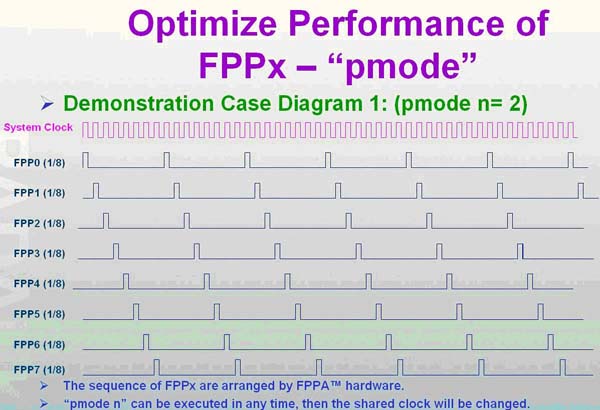
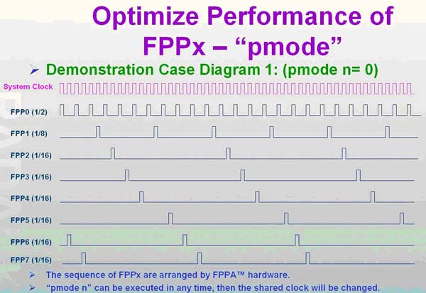
FPPA 最多可有8 颗MCU 同时平行处理, FPPA 有一“pmode”指令可调整每一MCU 的速度,FPPA 根据“pmode”由硬体强制去分配的每一MCU 的bandwidth 来完成类似软体RTOS 的功能( 如下表),完全不用写软体的RTOS.
| pmode | FPP0 | FPP1 | FPP2 | FPP3 | FPP4 | FPP5 | FPP6 | FPP7 |
| 0 | 1/2 | 1/8 | 1/16 | 1/16 | 1/16 | 1/16 | 1/16 | 1/16 |
| 1 | 1/4 | 1/4 | 1/8 | 1/8 | 1/16 | 1/16 | 1/16 | 1/16 |
| 2 | 1/8 | 1/8 | 1/8 | 1/8 | 1/8 | 1/8 | 1/8 | 1/8 |
| 3 | 1/2 | 1/8 | 1/8 | 1/8 | ||||
| 4 | 1/4 | 1/4 | 1/4 | 1/8 | 1/8 | |||
| 5 | 1/16 | 1/4 | 1/4 | 1/4 | 1/16 | 1/16 | 1/16 | |
| 6 | 1/16 | 1/2 | 1/8 | 1/16 | 1/16 | 1/16 | 1/16 | 1/16 |
| 7 | 1/8 | 1/2 | 1/8 | 1/8 | 1/8 |
如下图为 pmode =2 , 平均每一 MCU 分配 1/8 system clock
下图为 pmode=0 ,FPP#0 = 1/2 system clock, FPP#1 = 1/4 system clock, FPP#2-FPP#7 = 1/16 system clock ,每个 FPP 的 cycle 如下
FPPA暂存器 (Registers) 说明
|
PPA 共有33 个暂存器(不同系列暂存器略有不同),其中address 0x10 – 0x32 各为I/O Port A – Port E 的控制暂存器,故真正要注意的register 只有13 个,不 像其他MCU,周边控制(如PWM,I2C,UART 等)的register 就好几拾个,故FPPA 很容易学习U. 13个register 中比较容易引起误解,或datasheet 描述不易理解的地方特别提出说明.
“sp” & “flag”: 由于 FPPA 有8颗 MCU,故每一 MCU 看到的 “sp” & “flag” 的值是不一样的值.
“fppen”: 由于 FPPA 有8颗 MCU,但并不是每个应用 8 颗 MCU 都要去 enable, 故可用 “fppen” register 去控制那些 MCU 需要 enable.
gdio”: register “gdio” 可以做下列二种应用
当warm-boot 或cool-boot的判断用:由于FPPA 开机或reset 时, “gdio” 的值不会去变更,故程式执行中可故意写入一个值给“gdio”,而在程式开始的地方 去判断“gdio” 的值是否为程式执行中所写入的值即可判断MCU 是否是第一次开机或是reset 再开机.
让MCU & MCU 间的沟通更有效率:“wait0” 和“ wait1” 指令除了可对I/O 处理外, 也可对“gdio” 暂存器处理, (Ex.: “wait0 gdio.x”) , 例如在MCU#1 中把“gdio.x” 设为0 或1, MCU#2 用“wait0” 或“wait1”指令去做条件的判断亦可达到MCU#1 和MCU#2 之间的沟通 .
FPPA 软体规划
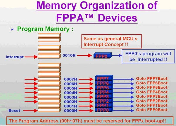
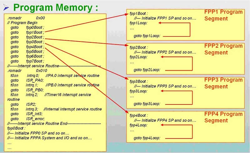
如上图所示,和大多数的MCU 一样,FPPA 也有所谓“中断向量表”的概念,只是一般MCU 的中断向量是“中断副程式” 的进入位置,FPPA 的中断向量是各FPP 的进入位置. 如上图中address 0h-7h 分别为FPP#0-7 的进入位置,address 0x10 才是“中断副程式” 的进入位置,故其程式写法如下
FPPA 指令介绍 (Instructions Set)
| FPPA Instructions Set | |
| Data Transfer Instructions (16) | |
| Instruction | Function |
| mov a,I | Move immediate data to ACC。 |
| mov M,a | Move data from ACC to memory |
| mov a,M | Move data from memory to ACC |
| mov a,IO | Move data from IO to ACC |
| mov IO,a | Move data from ACC to IO |
| pushw index | Move the content of index to be the content of stack pointer |
| pushw pcN | Move the content of program counter of Nth FPP unit to be the content of stack pointer |
| popw index | Restore the content of stack pointer to be the content of index |
| popw pcN | Restore the content of stack pointer to be the content of program counter of the Nth FPP unit |
| ldtabh index | Load high byte data in OPT to ACC by using index as OPT address |
| ldtabl index | Load low byte data in OTP to ACC by using index as OTP address |
| ldt16 index | Move 16-bit counting values in Timer16 to memory which is addressed by index |
| stt16 index | Store 16-bit data from memory addressed by index to Timer16 |
| idxm a,index | Move data from specified memory to ACC by indirect method |
| idxm index,a | Move data ACC to specified memory by indirect method |
| xch M | Exchange data between ACC and memory |
| Arithmetic Operation Instructin (20) | |
| add a,I | Add immediate data with ACC, then put result in ACC |
| add a,M | Add data in memory with ACC, then put result in ACC |
| add M,a | Add data in memory with ACC, then put result in ACC |
| addc a,M | Add data in memory with ACC and carry bit, then put result in ACC |
| addc M,a | Add data in memory with ACC and carry bit, then put result in memory |
| addc a | Add carry with ACC, then put result in ACC |
| addc M | Add carry with memory, then put result in memory |
| nadd a,M | Add negative logic (2's complement) of ACC with memory |
| nadd M,a | Add negative logic (2's complement) of memory with ACC |
| sub A,I | Subtraction immediate data from ACC, then put result in ACC. |
| sub a,M | Subtraction data in memory from ACC, then put result in ACC. |
| sub M,a | Subtraction data in ACC from memory, then put result in memory |
| subc a,M | Subtraction data in memory and carry from ACC, then put result in ACC |
| subc M,a | Subtraction ACC and carry bit from memory, then put result in memory |
| subc a | Subtraction carry from ACC, then put result in ACC |
| subc M | Subtraction carry from the content of memory, then put result in memory |
| inc M | increment the content of memory |
| dec M | Decrement the content of memory |
| clear M | Clear the content of memory |
| mul | Multiplication operation. An 8x8 unsigned multiplication will be executed. |
| Shift Operation Instructions (11) | |
| sr a | Shift right of ACC |
| src a | Shift right of ACC with carry |
| sr M | Shift right the content of memory |
| src M | Shift right of memory with carry |
| sl a | Shift left of ACC |
| slc a | shift left of ACC with carry |
| sl M | Shift left of memory |
| slc M | Shift left of memory with carry |
| swap a | Swap the high nibble and low nibble of ACC |
| swap M | Swap th high nibble and low nibble of memory |
| Logic Operation Instructions (16) | |
| and a,I | Per logic AND on ACC and immediate data, then put result in ACC |
| and A,M | Per logic AND on ACC and memory, then put result in ACC |
| and M,a | Per logic AND on ACC and memory, then put result in memory |
| or a,I | Per logic OR on ACC and immediate data, then put result in ACC |
| or a,M | Per logic OR on ACC and memory, then put result in ACC |
| or M,a | Per logic OR on ACC and memory, then put result in memory |
| xor a,I | Per logic XOR on ACC and immediate data, then put result in ACC |
| xor a,M | Per logic XOR on ACC and memory, then put result in ACC |
| xor M,a | Per logic XOR on ACC and memory, then put result in memory |
| not a | Per 1's complement (logical complement) of ACC |
| not Mry | Per 1's complement (logical complement) of memo |
| neg a | Per 2's complement of ACC |
| neg M | Per 2's complement of memory |
| comp a,I | Compare ACC with immediate data |
| comp a,M | Compare ACC with the content of memory |
| comp M,a | Compare ACC with the content of memory |
| Operation Instructions (6) | |
| set0 IO.n | Set bit n of IO port to low |
| set1 IO.n | Set bit n of IO port to high |
| tog IO.n | Toggle bit state of bit n of IO port |
| set0 M.n | Set bit n of memory to low |
| set1 M.n | Set bit n of memory to high |
| swapc IO.n | Swap the n-th bit of IO port with carry bit |
| Conditonal Operation Instructions (13) | |
| ceqsn a,I | Compare ACC with immediate data and skip next instruction if both are equal |
| ceqsn a,M | Compare ACC with memory and skip next instruction if both are equal |
| cesn M,a | Compare ACC with memory and skip next instruction if both are equal |
| t0sn IO.n | Check IO bit and skip next instruction if it's low |
| t1sn IO.n | Check IO bit and skip next instruction if it's high |
| t0sn M,n | Check memory bit and skip next instruction if it's low |
| t1sn M,n | Check memory bit and skip next instruction if it's high |
| izsn a | increment ACC and skip next instruction if ACC is zero |
| dzsn a | Decrement ACC and skip next instruction if ACC is zero |
| izsn M | Increment memory and skip next instruction if memory is zero |
| dzsn M | Decrement memory and skip next instruction if memory is zero |
| wait0 IO.n | Go next instruction until bit n of IO power is low; otherwise, wait here |
| wait1 IO.n | Go next instruction until bit n of IO power is high; otherwise, wait here |
- FPPA 共有97 个(不同系列,指令略有增减)1T RISC type 功能强大的指令.大部分的指令看datasheet 就知道其用法,不再多叙,这里只介绍比较容易引起误解,或datasheet 叙述不 容易理解的地方特别提出说明
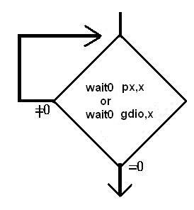
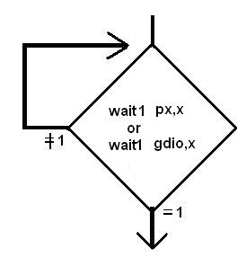
wait0,wait1: 只能针对I/O 或register “gdio”,但不能对记忆体, 其功能如流程图所示,一直要等到I/O 或gdio.x =0 或1 成立才往下继续执行 ,因传统的MCU,只有一颗MCU,故无法去实现这种指令,否则如果条件不成立,程式就一直停在那,形同“当机”.
delay :直接delay x 个system clock 才往下继续执行, 例如system clock = 8Mhz,pmode = 0,FPP#0 执行“delay 100” =100*1/4M = 25us,但FPPA#1执行“delay 100” = 100 * 1/1M = 100us.
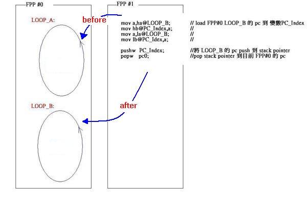
pushw,popw: push & pop 程式指标
由于PFPA 是一颗8 核心的MCU,不同MCU 间可更改彼此的程式指标“pc”, 来达到强迫其他MCU 去执行某段程式的路径之目的,但要小心运用,否则容易破坏程式的结构. 下例中的FPP#0 原本只会在LOOP_A无穷的回圈中打转, FPP#1 经由“pushw” 和“popw” 改变了FPP#0 的程式指标, 让FPP#0 变在LOOP_B无穷回圈中 打转.
台湾应广科技的杰出创始人唐总、销售总部的领航者李总以及业务部门的精英刘总近日亲临我司,与我们团队展开了一场深入且富有成果的交流。在这次会晤中,我们深入探讨了当前芯片销售与推广领域的挑战与机遇,以及各级代理商在市场中面临的具体需求和挑战。
唐总以其丰富的行业经验和前瞻性的视野,为我们揭示了科技发展的最新趋势和市场变化。他强调,随着技术的日新月异和市场竞争的日益激烈,代理商在芯片销售与推广过程中需要不断创新,紧跟市场脉搏,灵活调整策略,以满足客户多样化的需求。


